1
The Right Material
Ensuring optimal system performance
Selecting the right installation material is crucial for the efficiency of your industrial central vacuum system. Here is why our components have the right quality.
A Central Vacuum System, also called CVS, is a very sensitive and complex system, where many things could go wrong. That’s why it is important to address to a serious company, with extensive experience in designing, manufacturing, and installing industrial central vacuum systems.
This guide will give you some basic knowledge about what we do and why experience is the critical factor in order to provide you an efficient industrial central vacuum cleaner:
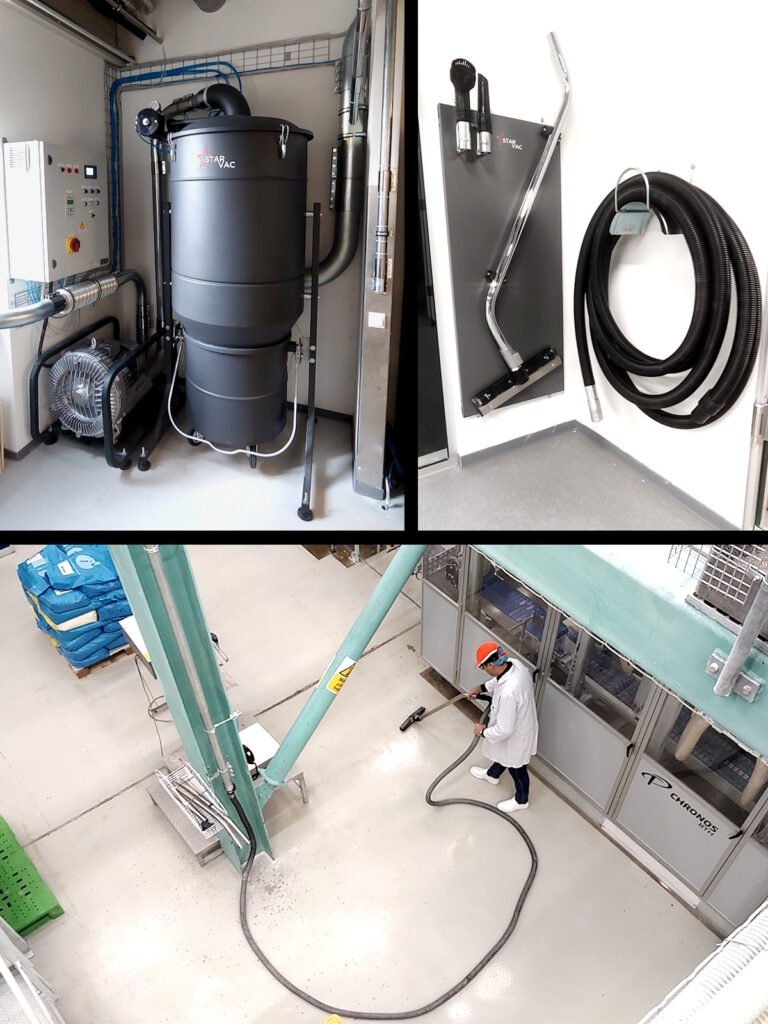
Using right and high-quality materials is essential to ensure the CVS functions optimally, keeping your central vacuum cleaning system running properly, efficiently and reliably.
Wrongly planning a central vacuum system will result in many problems! ⦁ Choosing the right flexible hose diameter and length ⦁ Choosing the right air speed needed ⦁ Choosing how many simultaneous operators are needed ⦁ Calculating the needed total airflow ⦁ Right planning and dimensioning of the piping system ⦁ Is ATEX required?
Selecting the right installation material is crucial for the efficiency of your industrial central vacuum system. Here is why our components have the right quality.
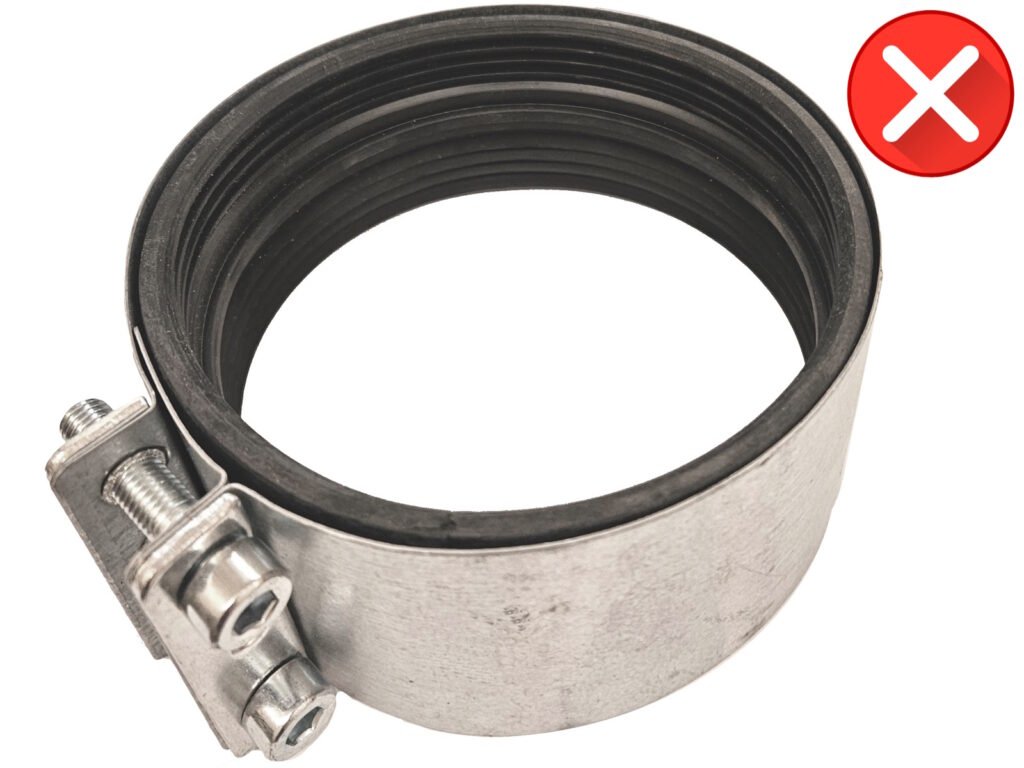
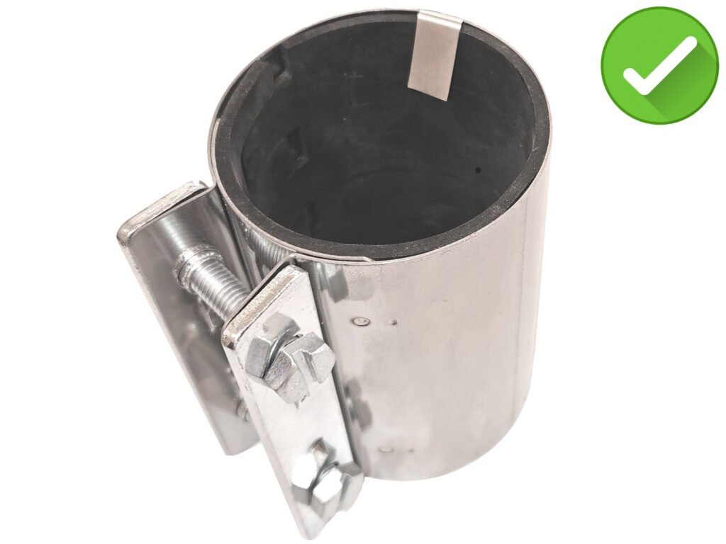
Our couplings are minimum 100mm long and include an earthing strap to discharge any electrostatic charge generated inside the piping system.
High mechanical stability and compliance with strict ATEX standards.
Some competitors use shorter, lower-quality couplings that lack proper grounding and stability, which in some cases even may not meet safety and performance standards.
Air inside our pipes travel at around 25 – 35m/s, which are 90 – 126 km/h.
Air inside our pipes travels at 25–35 m/s (equivalent to 90–126 km/h).
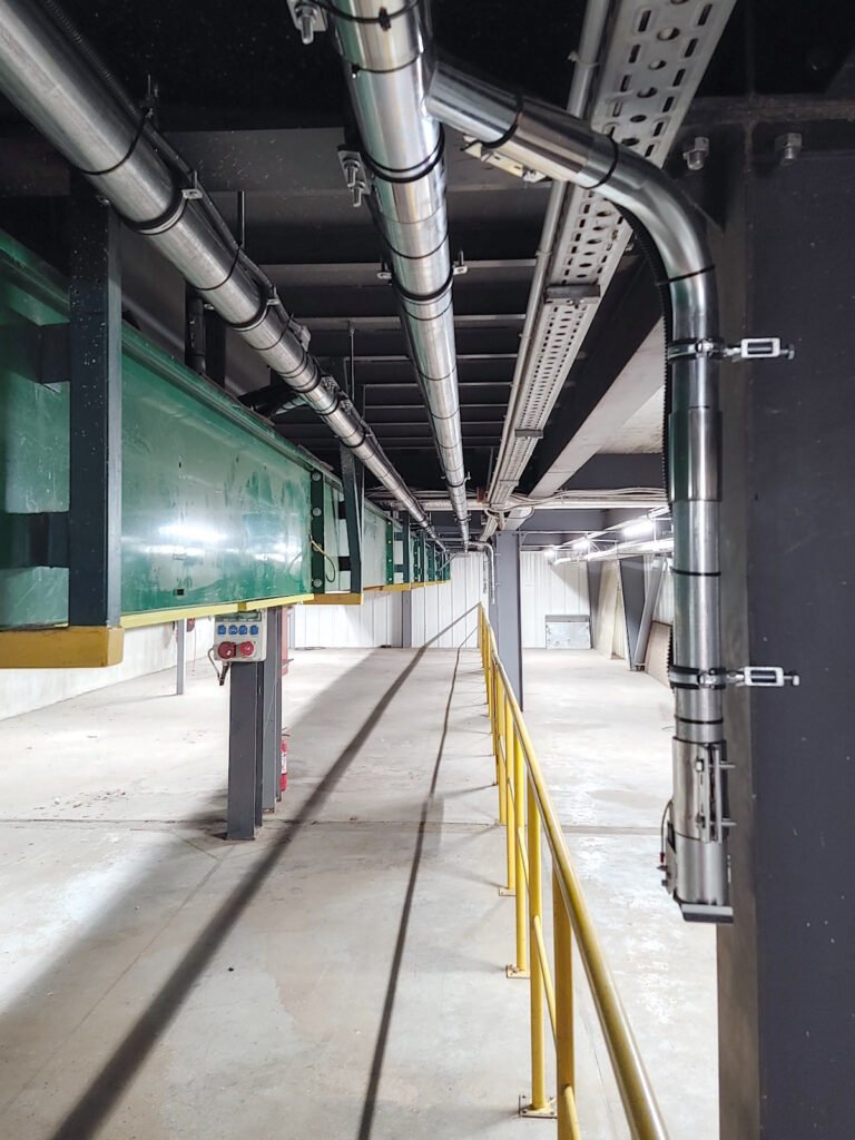
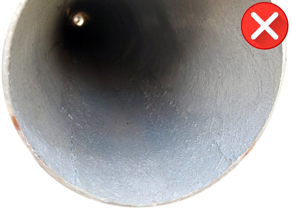
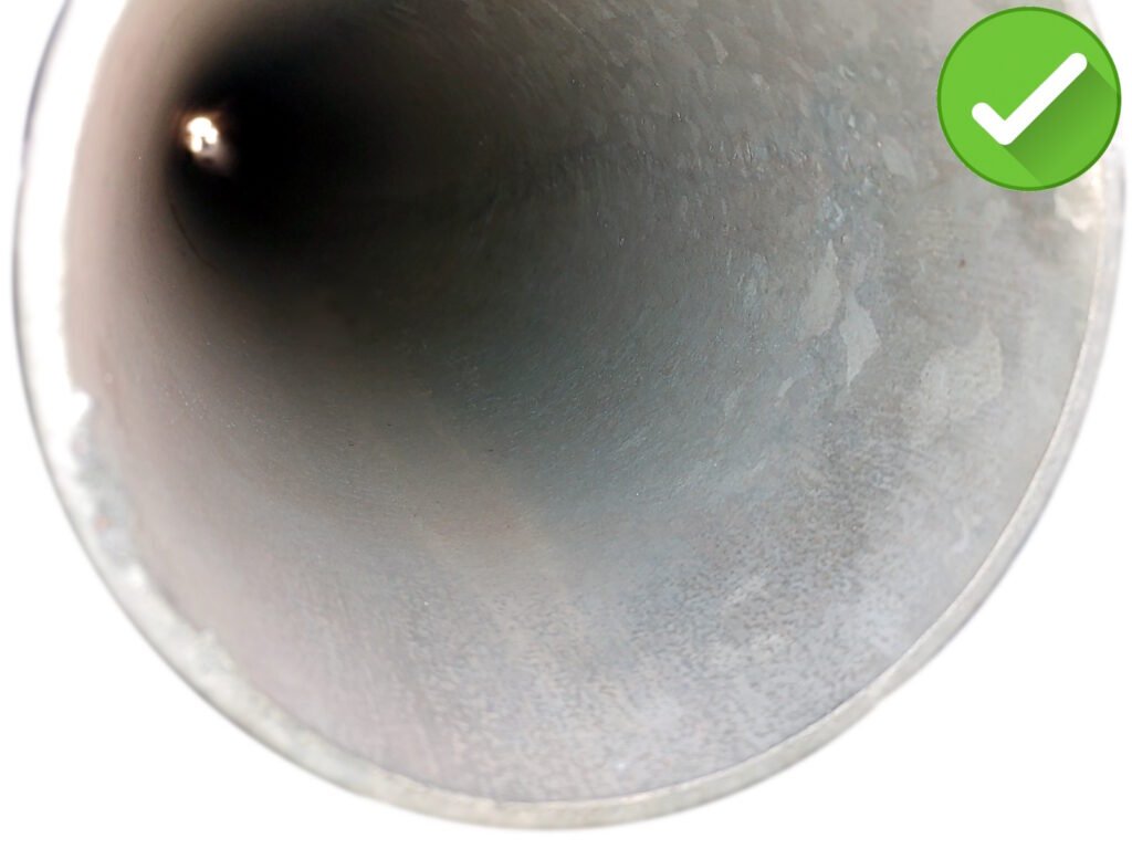
At these speeds, a smooth internal surface is crucial to minimize friction and pressure drop, ensuring optimal efficiency and performance. Smoother is better, as the air travels inside the pipe with less friction, less pressure drop, which results in a better efficiency and performance.
Our pipes are designed with an super-smooth interior, significantly reducing airflow resistance (pressure drop). Even small differences in surface smoothness can have a major impact on system performance.
What seems like a small difference actually has a big impact!
Actually, our systems can have 100m or more piping installed.
Most of competitor’s pipes often have rough, sandpaper-like interiors, increasing friction and pressure drop. This can reduce the system efficiency by a lot, ranging from 30 to 60%.
Larger is better, if you have the space!
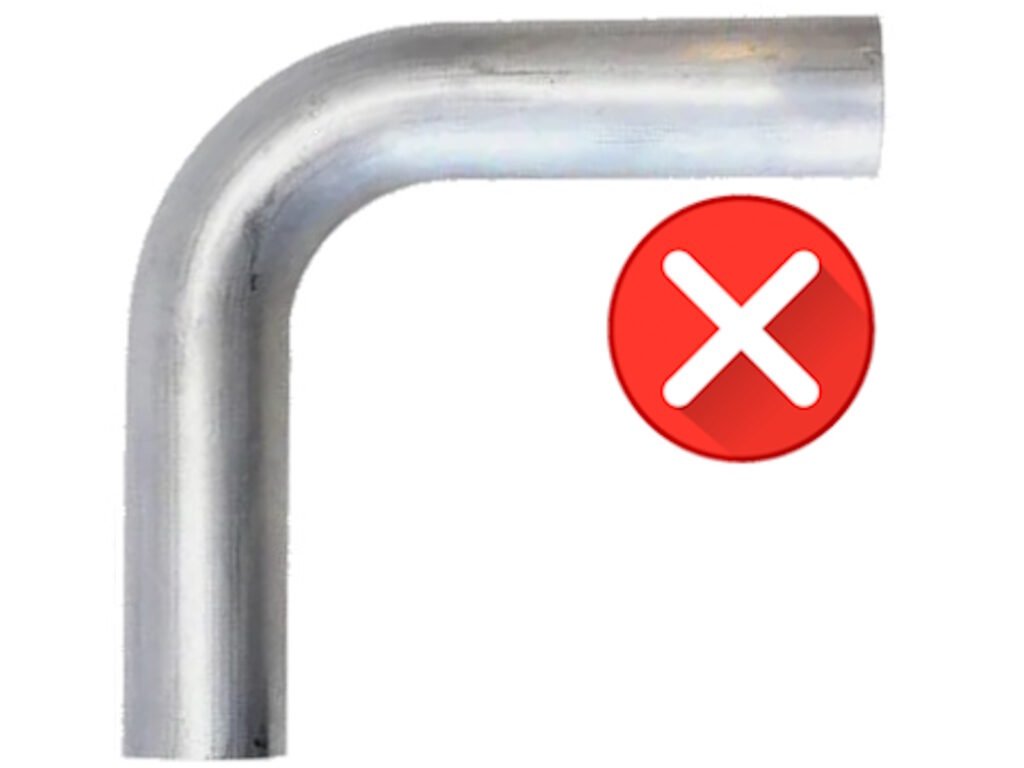
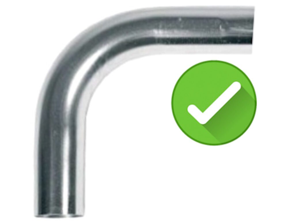
We usually use bends which have a minimum bend radius of 2,5 times the pipe diameter (R = 2.5*d), which minimizes pressure drop and wear.
While a larger bend radius is usually better, the most gains achieved within 2,5 times diameter.
Some competitors may use tighter bends, leading to higher pressure drop and increased wear.
| Radius multiplier value: | r/d = 1,5 | r/d = 2 | r/d = 2,5 | r/d = 3 | r/d = 3,5 |
| Pressure drop at 30m/s in Pa: | 167 Pa | 129 Pa | 108 Pa | 102 Pa | 97 Pa |
| Pressure drop per 0,5 x r/d increase: | -23% | -17% | -6% | -4% | |
| Accumulative, total pressure drop | |||||
| difference starting at r/d=1,5: | -23% | -35% | -39% | -42% |
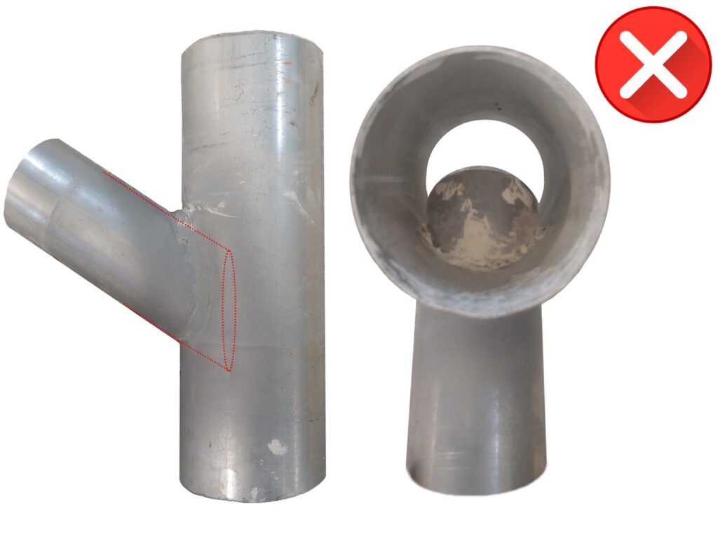
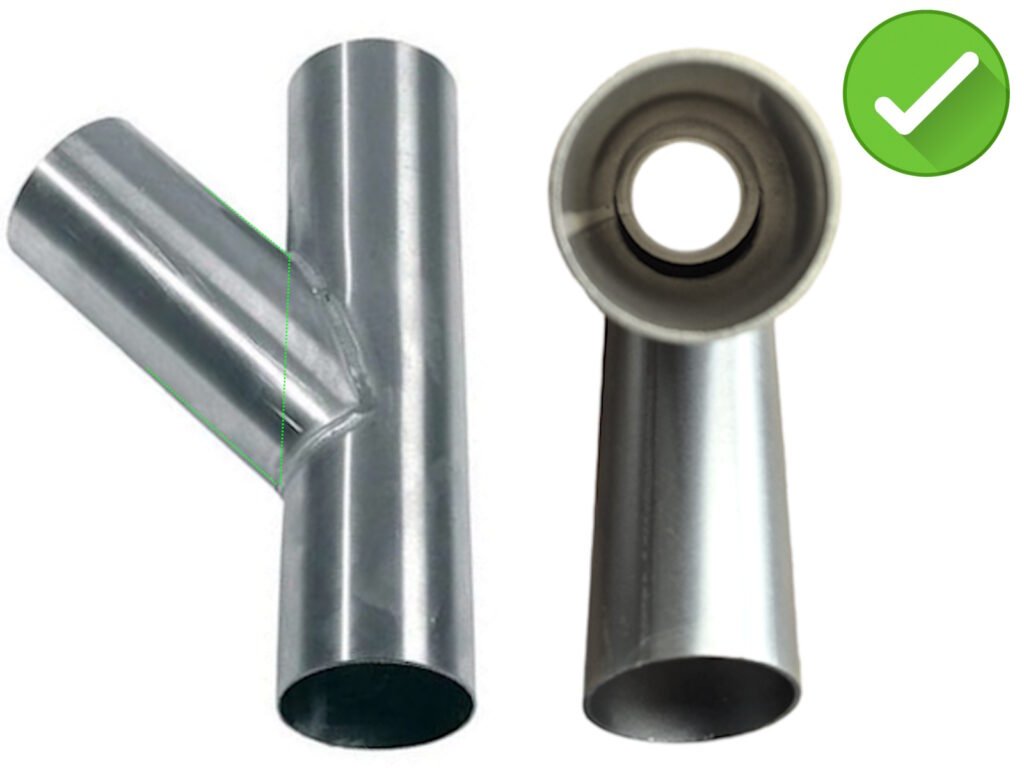
Our branch pipes are precisely designed so the side pipe aligns flush with the start of the main straight pipe, preventing airflow obstructions and turbulences.
Some competitors might not ensure this alignment, potentially causing blockages and reduced system performance.
We have seen pipe branches as below, where performance is reduced significantly through the whole system!
Choose high quality / high-performance material only, so that you have less problems, and a better, more
efficient central vacuum system.
A reliable vacuum system with reduced maintenance and operational costs and higher vacuum power!
Poor planning of a central vacuum system can lead to serious inefficiencies and costly mistakes. To ensure optimal performance, key factors must be considered:
2.1 Choosing the right flexible hose diameter and length
2.2 Choosing the right air speed needed
2.3 Choosing how many simultaneous operators are needed
2.4 Calculating the needed total airflow
2.5 Right planning and dimensioning of the piping system
2.6 Is ATEX required?
To start, a suitable diameter for your vacuum tools must be chosen, which depends by the granulometry and /or quantity of material to be vacuumed.
A longer flexible hose needs more space for storage and it is less convenient for handling.
Shorter is the flexible hose, then you need more suction inlet points to cover same area and more interruption to plug-in and out.
Think about the best compromise for your production line!
As a rule of thumb, a value between 7 and 12m is a good compromise.
There are 4 main diameters available. Please note that those values are INTERNAL diameters of the hoses:
d40, d50, d80 and d100.
| Diameter | Use for | Handling | Power | Weight |
|---|---|---|---|---|
| d40 | Fine dust, powders, flour, polymer pellets, wood dust, small particles (<3cm) | ++ | ++ | + |
| d40 | d50 is similar do d40, but for larger quantities. Large quantities of: Flour. Polymer pellets. Wooden dust. Some small particles with size less than 4cm in diameter. | + | + | ++ |
| d40 | Heavy duty: Use for vacuuming really large spillages. Heavy duty applications. Larger particles with maximum size 6-7cm | +- | +- | +++ |
| d40 | Ultra heavy duty: Huge amounts of dust to be vacuumed. Large particles / debris. Heavy and bulky material. | -- | -- | ++++ |
Choose a set diameter relative to the above table.
Airspeed is critical for maintaining a properly working vacuum system and preventing material build-up in
the piping system.
This is a value, only you can know and depends by the labour organisation and workflow!
How many simultaneous operators do you wish being in operation at any given time?
How much staff do you have and how many will be expected cleaning at the same time?
Typically, systems range from 1 to 8 simultaneous operators, but 20 or more operators can be supported with proper system design.
It really depends on what you need!
Required airflow per single operator:
| Hose Diameter [mm] | Normal Duty Airflow [m³/h] | Heavy Duty Airflow [m³/h] |
|---|---|---|
| 40 | 125 | 195 |
| 50 | 230 | 310 |
| 80 | 590 | 780 |
| 100 | 920 | 1230 |
Example of total airflow calculation:
If 3 operators use d50 vacuum sets in Normal Duty (ND) mode, the total required airflow is:
3 * 230 m³/h = 690 m³/h with around 200 mbar vacuum power.
Selecting the correct piping diameter is one of the most critical factors for properly functioning industrial central vacuum cleaning system.
As you have learned above, it´s important to have proper material and proper understanding of how much
airflow is needed, but we have not dived into the planning of the diameter of the metal piping system used
for an industrial central vacuum cleaning system yet.
This part is by far the most important task!
We will not show the planning in detail, as it contains a lot of know-how, confidential information and is
one of our core competencies, anyways please find below some general guidelines:
Below values are mostly OK, but many other considerations will also play a role in proper piping diameter
dimensioning.
Why Is Expert Planning so Important?
Larger pipes reduce resistance but result in lower airspeed, increasing the risk of material accumulation and clogging. For example, if only one vacuum set is running on a d76mm pipe, air velocity may drop below 7m/s, leading to material build-up inside the piping.
Proper system design requires balancing pipe diameter, airflow speed, and suction power to ensure optimal operation.
Getting the dimensions right is no simple task—our extensive experience helps prevent design flaws that could lead to a not properly working central vacuum system and customer unsatisfaction.
Our team of experts can accurately size and design the entire piping system, including isometric drawings and detailed & tailored performance calculations.
Want to know how to properly dimension a piping system in detail?
The answer is: Let the professionals properly dimension it to avoid problems
With our expertise, we can quickly deliver a well-designed piping system, complete with all necessary performance data and calculations, and customers will be happy with a properly functioning industrial central vacuum system ☺
Most dust types are potentially explosive, requiring a central vacuum system compliant with strict ATEX safety regulations
Some examples of explosive dusts are:one of our core competencies, anyways please find below some general guidelines:
Flour. Sugar. Milk powder. Wood dust. Pharmaceutical Powders. Coal dust. Polymer dust (PVC,
Polyethylene…). Textile and Cotton Dust. Chemical Powders. …
Below values are mostly OK, but many other considerations will also play a role in proper piping diameter
dimensioning.
Pressure drop is one of the most critical factors in designing an efficient industrial central vacuum system. It refers to the loss of vacuum power as air moves through the system due to friction, turbulence, and obstacles.
Since pressure drop affects suction performance at the vacuum tool, an accurate calculation is essential to
ensure optimal operation of the whole system.
If the system experiences too much pressure drop, the vacuum efficiency decreases, leading to poor
material pickup capacity and increased energy consumption.
Factors Influencing Pressure Drop
Several factors contribute to pressure drop in an industrial vacuum system:
Airflow speed and pipe diameter → Higher speeds in small pipes create more resistance.
Pipe length and number of bends → Longer pipes and many ells (90° or 45°) increase friction.
Pipe material and surface roughness → A smoother internal surface is better.
Flexible hoses quality → Some flexible hoses are not smooth internally, increasing friction.
Filtration system → Filters can create significant resistance, especially when clogged.
Basic Example of Pressure Drop Calculation
Let’s consider a central vacuum system designed for one operator using d40 vacuum tool sets, with an airflow of 125 m³/h.
The system consists of:
Piping system: 30m of 50mm straight piping, 5 x 90° bends, 10m of flexible hose (d40).
Main filter unit with a resistance of 10 mbar
Using pressure drop coefficients for each component, we can calculate:
Straight pipe losses → 49 mbar
Bends → 12 mbar
Flexible hose losses → 80 mbar
Filter resistance → 10 mbar
Total estimated pressure drop: 151 mbar
Why It Matters
If the available vacuum power were only 140 mbar, the remaining suction at the tool would be too weak to effectively collect dust and debris.
In this case, a larger pipe diameter or a more powerful blower would be required to compensate for
pressure losses.
Conclusion
Proper pressure drop calculation ensures the right blower power is selected to maintain good suction
power.
Undersized systems lead to inefficiency and performance loss, while oversized systems waste energy.
This website uses cookies so that we can provide you with the best user experience possible. Cookie information is stored in your browser and performs functions such as recognising you when you return to our website and helping our team to understand which sections of the website you find most interesting and useful.
Strictly Necessary Cookie should be enabled at all times so that we can save your preferences for cookie settings.
If you disable this cookie, we will not be able to save your preferences. This means that every time you visit this website you will need to enable or disable cookies again.